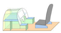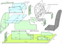
Basic construction and dimensions are shown below:


The simpit is designed as General Aviation single seater. The visual setup is
multi purpose: One 18" screen for cockpit & scenery view or cockpit
instruments
view only to be be combined with a separate outside scenery view (see:
Visuals)
Limited height and the 18" panel in front makes a
flight yoke rather difficult, as it would have to protrude through the
panel. Therefore I decided to use a flight stick.
Since a stick is mostly flown right-handed, the
throttle control had to be
at the left, as well as the most often used controls, like
gear, trim,
flaps,
mixture, prop pitch.
Mouse control is needed for some (non-flying) commands. There is a small
place for the mouse at the right side. Also at the right are some small
keypads, for simulator and menu selection commands. I also put the switches
for auto-pilot activation there.
Rudder pedals are mounted on the floor board
in front, with the centering bungee cords at either side.
The floorboard is long enough to mount the seat as well. The seat was
made from an old high-backed office chair, that is mounted under some angle
to a wooden base. For normal flying, the chair does not need to be bolted on
the floorboard, but for motion platform use this would definitely be necessary. To
get in and out of the cockpit, the chair has to be pushed backward, so a
chair slide mechanism like in a car would be a nice addition.
The chair is equipped with a big transducer,
for feeling of engine rumble and aircraft vibration.
All electronics are mounted in the front section of the Simpit:
Right side view with hacked keyboard, hacked FF joystick, FF power buffer
and power supplies.
Left side view with Transducer amp and rear view of front mounted controls
like starter key, parking brake, headphone and microphone jacks. Also
visible are the potmeters for transducer volume control.
The front view of the electronics inside: LCD panel + power brick, and the
toggle to momentary relays + trim wheel interfacing circuitry mounted to the
side boards. The picture with front board added shows how all wiring to PC
and AC mains comes out.
Note: Originally, the front board was straight, like in the drawings. When I
did the experiment with multiple projectors,
the projector beams just hit the front of the simpit, therefore I modified
the front top slightly backwards.
For covering the 'hood' I used 3mm triplex. The right shape can be found by
bending it over the hood frame and drawing the outline from the inside. The hood has some 30mm
slack at the faceplate side, to have some kind of glare shield function. With this
edge, you can slide-on some isolation foam tubing, to make a nice soft
surrounding edge (just in case you crash).
I have also experimented with adding some cockpit lighting, activated by the
cockpit light switch, shining from under this foam lining. LED's and
lamps are not satisfactory, as they emit bundles of light. Some diffusing
would be needed. Maybe the small CFL backlights + driver from LCD panels
could be used.
Update: The Simpit is now mounted on the
DIY Motion Platform III