Update: I replace the HAT switch by axis controlled view, see Modified axis HAT
A flight stick construction is very similar to the actual joystick, but since the actual stick is much longer than the joystick, and centering forces also need to be stronger, it is not always possible to use the original joystick mechanics.
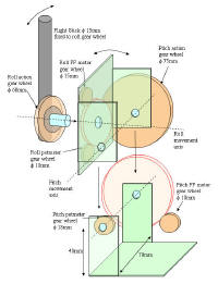
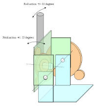
For my flight stick, I made a complete new mechanical design, with rather heavy duty materials to make sure it would be strong enough and not easily wear out. Just as with the flight yoke, the X and Y axis movements have to be transferred to potmeter rotation. Similar to the flight yoke, it is most convenient to have the pitch axis potmeter fixed on the base, and have the roll axis potmeter move together with the pitch motion. Since flight stick axis movement is much smaller than with a flight yoke and both movements are rotational, I used gear wheels for axis to potmeter rotation. By using heavy duty gear wheels, the force feedback could also be applied to the same gear system. Below drawings show the principle of the stick design.
Some design details: The gear ratio on the elevator FF is 16/80, with a
total stick length of 44cm. Spec of the (second hand) motor that I used: (Glentek GM2340-15)
http://www.glentek.com/glentek/dcsel.aspx
Power:
150W, torque: 0.133Nm/A, rated current : 2.5A, DC resistance 2.8 Ohms. I get
~1.5N/A stick force. At 4A motor current I get ~ 6N stick force.
The gear ratio on the Aileron is 14/60. I don't have spec of the motor, but
the force here is much less than the elevator, I guess about 1.5 ~ 2N


Flight stick mechanical design. I used parts of LCD monitor pedestal
base.
Front view with roll gear. Here you can see the roll axis gear with roll
axis potmeter and roll axis force feedback motor.
Front view without roll axis gear mounted
There is a slot in the plate which is used to set the end-limit stops of the
roll axis movement.
Side view without roll axis gear mounted
Back view: You can see a black pin sticking out of the pitch axis gear
wheel: It is used for the "pull-up" end stop. The pitch rotation friction is
controlled by using bolds, nuts and tension rings on both hinges.
A detail of the stick to roll gear wheel: I used plumbing materials: Brass
tubes hard-soldered on a plate, which is fixed to the roll gear wheel (using
epoxy putty and screws) The plate also includes the bold for fixing the
assembly to the pitch plate. The stick is 15mm diameter copper pipe that
fits in the brass tubes, fastened with screws.
View of the other side. An important detail is the fixation of the roll
assembly to the pitch plate: The bold uses special rings that snap into the
plate gaps. I also have tension rings is the assembly: The torque by which
the nut is tightened will control the friction of the roll movement on the
pitch plate. It needs to move rather smoothly if you want to be able to feel
the force feedback details. But if the tension is too low, the stick's pitch
movement will not be firmly transferred to the pitch gear wheel, and the
pitch action will have some play.
Side view of the stick: Copper plumbing pipe 15mm diameter. Total length is
about 52 cm. I bend it by using a pipe bender (borrowed at the hardware
store). Black isolation tape was wound on the pipe to make it black.
The original Logitech Wingman
handle could easily be clamped on the taped pipe end. All wiring goes
through the hollow pipe. I originally used flat cable, but it picked up some
noise, so I covered it with copper tape. (not such a good idea, as it
resulted in shorts later on. Later I have changed to shielded 6-lead cable.
Here a view of the whole assembly mounted in the box. The pitch force
feedback motor is quite strong, and needs to be firmly mounted on the box
floor. This holds also for the metal base plate of the stick. 5 screws were
needed to get the thing fixed sturdy enough to have a low tolerance force
feedback feeling.
All components assembled: A fan is needed to cool the roll FF motor. Even
so, it is not wise to hold the stick at the roll extremes for long periods
of time, as the motor dissipates considerably.
The bigger pitch FF motor can dissipate much more power, and there is no
heat problem here.
You can also see a small DIY transducer unit on the pitch plate. This is
used to give the stick some vibration. See: Adding
transducers.
The flight stick box with closed top. I added a black leather cover on the
stick to cover the hole, but still allow for ventilation.
The electrical joystick connections and force feedback motor drive are identical to the method used in the flight yoke. See Adding force feedback