.htm_cmp_capsules010_bnr.gif)
I have drawn the complete unit in Google Sketchup. The Sketchup file for the flight-yoke can be downloaded here. The file is build-up from several groups, so you can take the unit apart and check the dimensions of the various components.
The flight yoke consists of two units: The drawer construction and the
yoke + shaft. They can be connected in the middle.
The yoke shaft is hollow (12mm diameter ID) and the wiring for the button
switches and HAT switch passes through, to come out just before the middle
connection point.
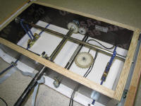
The drawer type construction has a movable carriage. It glides on 300mm
drawer rails. The yoke shaft rotation is transferred to the aileron potmeter
via gear wheels. The shaft sits in bearings, and has two shaft collars to
make the carriage move with pitch action. Felt patches are in between the
shaft collars and bearings to set some friction and avoid noise.
The carriage movement is transferred to the elevator potmeter via a chain
and sprocket wheel. (Junk from old copy machine)
The elevator centering force is done via a bungee construction: In mid
position, the bungees pull the center shaft down, and keep the carriage
centered with zero yoke force. When the yoke is pulled or pushed, the
bungees are gradually stretched more, and thereby gradually build-up the
counter force.
The elevator end-stops are mounted at the fixed drawer base on both sides.
The center shaft ends will hit the rubber end-stops after 95mm of travel
from center position.

The aileron is centered via a dowel connected to the yoke shaft. The dowel
is connected to a bungee tube, that goes to the side of the carriage. As
soon as the yoke is turned, the bungee tube is also gradually stretched
more, and this gives the automatic centering and aileron force. In close to
90 degree yoke position, the dowel will hit the end-stop bolts.
The movement of elevator and aileron can be seen here.
The yoke is made from 22mm OD copper pipe, that is hard-soldered at the
corners. The corners were then partly cut, and rounded with epoxy putty. The
wooden center block is actually two 18mm thick halves, with holes for the
two tube halves. They are screwed and glued to the rear wood. Also the yoke
shaft is glued into the rear wood block.
The buttons and HAT switch came from a junked gamepad. Not completely
authentic, but very functional.
Again I used epoxy putty to fix them to the yoke handles.
Since one often flies with one hand on the throttle, the left yoke handle needs to include the most often used buttons: HAT switch, reset view button and elevator trim buttons. The 4 switches on the right side are reserved for some (TBD) function. Actual yoke has only 2 buttons left: to be corrected.
The connection between yoke shaft and drawer construction needs to be
wiggle-free. Therefore I used one M3 bolt and 4 socket screws to fix it to
the 12mm drawer rod.
Update on the flight yoke:
I improved the HAT control on the yoke by adding a "reset view" button in
the center of the HAT:
I glued a very small tact switch in the center of the HAT with a flat
plastic button on top. The total height of this extra switch is very small,
only 4mm. The two switch wires go through the center of the HAT switch to
the bottom PCB.
The yoke now has a center support guide, with Teflon bearing to make it
run smooth.
The center guide is made of copper pipe, bend to fit the yoke shaft
diameter.
The Teflon pads came from an old mouse, and are fixed with double sided
tape.
The yoke shaft now has a polished aluminum tube, which goes over the steel
shaft. It is very smooth, and also looks good.
All yoke components are shown above. The yoke can still be completely taken
apart for future modifications.
Future modifications: To add a 2nd carriage, that moves the bottom pulleys front-aft for shifting the elevator center point, based on elevator trim. Also a bungee tightening system can be added for force-airspeed relation.