As
always, I will bring my Motion Cockpit IV for live demo during the complete
FSweekend 2019 in Lelystad. Please look me up in the main hall for a chat and a flight.
For the die-hards, I have installed a Carrier landing and take-off addon, please see this video. If you are up to this challenge, let me know when you visit my stand.
A video presentation of the various systems of the Motion Cockpit can be
seen here.
______________________________________________________________
Although platform III performs pretty good, it has a rather large
footprint. (about 2.5x2.5m including actuators, which takes about the whole
attic floor space). I have therefore been looking for way to reduce
the footprint, and still achieve acceptable performance. I came across
this video from
InMotion
Simulations. A particularly clever construction, that uses a triple
Sarrus linkage in a triangle setup. This construction is self-stable, can
achieve good actuator travel, while the total footprint is minimized. Due to
the scissors mechanism, the actuators have very low height in down position.
Since I don't have the US$ 35,000 I thought building one would be
quite possible, and a good challenge. (got to keep busy)
My goals for this 3DoF platform:
Single seater, payload about 160kg, weight-balanced, footprint 1.5x1.5m. Other considerations: Good response, low noise, standard materials, price about 800 Euro, most materials sourced from Taiwan.
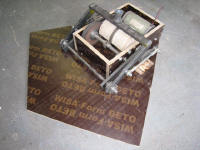
Below pictures show a fully functional wooden scale model, (about scale
2:3)

The construction includes the balancing system, via bungee cords
that are wound on the wooden drum during platform lifting.
12V powered tests with
30kg ballast went well, no real issues discovered. (see video's) As I found out, the
triple Sarrus stability mainly determined by the bearing construction in the
wooden levers.
(This prototype was shown at FSWeekend 2009)
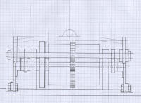
The drawings of the full scale size actuator construction are shown
below. The box is still made of wood, but the rest of the materials are
solid steel.


The crank and lever size have been optimized for max travel while keeping
the forces reasonable and travel relatively linear. Actuator travel
33cm max. Probably 30cm useful travel.
Some drive calculations:
Motor torque is 0.375Nm/A. RPM @ 36V: 936 rpm = 15.5 rounds per second.
Gear ratio belt: 3:1, Gear ratio spruce gear: 4:1
Final crank speed: 1.3 rounds per second. Actuator speed: about 33cm in 0.55
seconds (0.6m/sec), which is about the same as my #3 platform.
Torque on final crank shaft: 0.375*3*4=4.5Nm/A.
36V battery with ~ 1.5 Ohm stall resistance = 24A motor current. Final crank
shaft max torque: 108Nm. With crank arm of 7.5cm, I should get a crank force
of 1440N. Due to scissors construction, the actuator output force is reduced
to about 60%. this means max output force is 864N per actuator. Total
pushing force 2592 N.
Note this calculation assumes no losses. Actual force will be lower. But the
initial numbers are not bad.
Initial construction pictures:
Here are some pictures of the initial construction. Not all distances are
fixed yet, so some items are pending.
I have chosen to fix all parts with bolts initially. When all fits well, I
can weld the parts for more strength.
The wooden case is made of 18mm heavy duty multiplex
All gears and cranks are fixed to the shafts with 5mm keys to eliminate
backlash. The gear to gear distance is made adjustable, to be fixed in final
construction.
The side cranks are made from sprocket wheel with a steel plate bolted on. A
different plate could be used when other distances are needed.
The bearings are fixed to the sides and metal bars by means of the shaft
collars. The double bearings on the metal bar will result in a very stiff
hinge construction.
Completed crank to lever linkage. Cut-off part of the sprocket wheel.
Wooden drum made from 8 multiplex circles. Fixed to gear wheel with four M8
threaded rods.
Hit a bit of a snatch: when testing the bungee weight balance, the force
non-linearity was unacceptable. Luckily the wooden drum construction is
flexible: by changing the drum shape, a linearity correction is possible to
obtain a more constant force over actuator travel.
Some measurements are needed:
The above graph shows the (torque) rotation force on the crank top over full
actuator travel: in starts at lowest position, (crank almost at 9 o'clock as
viewed from side-view of sketch, rotating counter clockwise to max
position). It is interesting to see that the required rotation force is at
maximum when crank is at 180 degrees (3 o'clock position), and close to top,
the force quickly goes to zero.
The max required bungee counter force is 33kgf for 20kg payload, and will
need to be ~ 90kgf for 55kg payload per actuator.
It is clear that a bungee wound over the circular wooden disk is not going
to give a correct counter force. So the radius of the wooden drum has to be
modified at certain angles to compensate for the non-linear force.
After some drawings and trials, I came to the following design:
The wooden drum actually needs to be a small section only. The bungee
attaches at a point where it stabilizes the crank to its top position. This
also serves as a soft end-stop. Then when the crank rotates to the 3 o'clock
position, the bungee will pull with maximum radius, thus achieving max
opposing crank force. After further rotation, the bungee moves inward
towards the shaft, thereby reducing the radius, and reducing opposing crank
force. At crank bottom position, the bungee folds around the shaft, and
radius is minimal, so also force is minimal. The rounding edge on the
wood makes for a gradual reduction of the force. I use a quarter
section wood to be able to fasten it to the gear wheel with two long bolts.
Above pictures show the setup with single wooden drum section. Top, max
force and bottom position shown.
I have now reserved space for 10 wooden drum sections, which means 20 strings of bungee. With 8mm bungee in
linear range, I have about 4kgf of pulling force per sting in max position.
That gives totally 80kg of pulling force. Since crank arm equals radius in
max force position, I have 80kg opposing crank force which equals 80*0.6 =
48kg of actuator weight balance force. This will balance a platform
weight of 144kg.
Final touches:
Added 10-turn potmeter as position pick-up via 15-teeth gear coupled to main
gear.
Added AMETEK DC motor. It sits on a carriage that can be moved to adjust belt
tension.
Completed one actuator: Everything fits! Ready for initial drive test with 16 strings of bungee.
Initial test of single actuator under full load:
http://www.youtube.com/watch?v=OS3gkMHAgEQ
Weight balance linearity not completely correct, but overall performance
quite good.
I have been thinking a while about the most suitable type of joint for
actuator-platform. A Boge-joint that is used in wind surf boards to join the
mast and board may be suitable. They can flex in all directions, are pretty
heavy duty, and also serve as a vibration isolator, to take the really sharp
edges out of the movement. Below a picture of such a joint, they come with
M10 threaded holes on both sides.
(edit: it was found that the Boge joints are too flexible in sideward
direction. This creates unwanted lateral motion during roll or pitch), so I
used the 10mm rod-end bearing for the joints to top platform.
The rod-end bearing platform joint is fixed to the actuator top bar with M10
bolt. The platform metal V profiles are connected to the bearing with an M10
threaded rod. Two M10 nuts keep the bearing in the middle. The nuts have to
be wedge-shaped toward the bearing sides to obtain the maximum useful
bearing movement. (+/- 20 degrees)
I have spend 'some' time to learn to draw the actuator and total setup,
using the free 3D drawing program
Google SketchUp.
It helps in planning the build for the rest of the system. Below some
drawings of various assembly stages of the actuator and total setup. If you
would like to have some of the Google SketchUp CAD files, let me know.
Mounted on floor board:
Footprint: 1.26m triangle shape. Actuator distance: 1m. Max Pitch/Roll
angles: 17 degrees, max heave: 32cm.
Google sketchup file of one actuator can be downloaded
here.
For some sense of scale, I added a real size pilot: It shows the compact
size of the actuator setup.
After lots of metal drilling and sawdust, all three actuators are
finished. Also cut the floorboards.


Mounted the top triangle frame. I used 10mm rod-end bearing for the
joints. (the rubber Boge joints were too flexible). The final structure is
sturdy and stiff in all directions.
Also added the full bungee weight-balance strings. I found that the original
setup overstretched the bungee, so I folded the bungee to increase length.
Each actuator now uses 13m of 8mm bungee cord for 50kg weight balance per
actuator.
After completion of the "Modular Simpit"
a quick try to see if everything fits:
Original drawing ceiling has
sufficient margin Good balance, no need to tighten the
bungees.
Tests with new PC show good performance. Servo gain needs to be reduced
due to less friction in the system.
See
initial test video
The rig also survived FSweekend 2010: 2 days of continuous use with some abuse from less skilled pilots. Structure is sound and robust.