Since this drive system requires an extra motion PC for translating the serial input to parallel port output, I have been thinking of ways to eliminate the extra motion PC.
Ian Hopper's 64SPU-1 card
hardware makes it possible to extract the motion data and drive 3
MD03 motor
controllers without the need of an extra PC.
This setup will also make
optimal use of the
BFF Motion
Driver software with
PID servo controller.
I have ordered the full bundle, which includes 64SPU-1 Servo Drive, the BFF I2C isolator card, the 12bit ADC Card and the V2 motion software.
The reason for using the I2C isolator card is based on earlier experience
with my home build system: I noticed that ground noise can be
considerable:
Switch-noise from the motor wires radiates HF noise and this
finds its way back through the ground wires into the system,
possibly
corrupting communication signals between the units. To reduce HF radiation,
I have now used shielded motor cables.
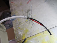
(Shielded motor cables can be hard to find, so I made my own):
I used TV antenna coaxial cable, and soldered the twisted motor cable
(18AWG) to the coax inner core.
Then gently pull the coax inner core at the other side of the cable, while
holding the cable other shield and isolation at both ends straight. Thus the
twisted wire can be pulled through and will replace the coax inner core. The
shield should be grounded to motor housing and battery minus.


I'm still using 10-turn potmeters for the position feedback, so the
12-bit ADC card seems a good way to achieve more accurate digital position signal
for the servo drive. The potmeter ends are connected between 0V and 5V.
The potmeter shaft on the 15-teeth gear should be adjusted such, that with
platform at mid position, the wiper voltage is 2.5V.
Since the servo in this system is software based, any glitch in the
software could lead to runaway in motor drive. End-stop switches are therefore
mandatory.
When activated, the end-stop switches will remove the 5V supply from the motor drivers.
Note that it does not have a latch action.
When end stop switch is triggered, the motor drive will stop, and platform
will move back to active range by bungee pull. As soon as end-stop switches
are closed again, the motor drivers will be re-initialized, and motor drive
will be active again. If continuous overdrive input exists, a hiccup
situation will occur.
To avoid this behavior, I added an extra
protection: I re-programmed the 64SPU card microprocessor software out of
range of the position
feedback. In default setting, when the ADC sees position
voltages close to upper and lower limit (5V and 0V) it will disable the
drive. I changed the the drive
shutdown levels just before the point where end-stop switches are triggered.
(Note that this is not a standard modification: Ian was kind enough to
provide the PICAXE 20X2 chip .bas file to me for modification. I then re-programmed the
chip, using the PICAXE free programming software)
The .bas file section which I reprogrammed:
if bit5 = 1 then
if pos1 < 6525 or pos1 > 13667 then err_feedback
end if
if bit4 = 1 then
if pos2 < 6525 or pos2 > 13667 then err_feedback
end if
if bit3 = 1 then
if pos3 < 6525 or pos3 > 13667 then err_feedback
end if
(6525 is my ADC low range limit value (1.59V) and
13667 is my ADC high range limit value (3.33V), which can be derived from:
potmeter value/5V * 20480) ; (Note that the bas file contains
two such sections, one for without ADC card and one for with ADC card)
Below are some pictures how I implemented the end-stop switches in Motion
Platform IV:

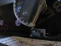
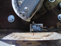
A wooden semi-circle was added to the right crank of each actuator: The
semi-circle has notches that push the switch when the crank is at its extreme positions.
One
SPDT micro-switch with roller lever is mounted on the floor plate for
each actuator.


Micro-switch at actuator top position not activated and activated:
Micro-switch at actuator bottom position not activated and activated
A short video on the drive limit and end-stop switch action can seen
here.
To keep things compact and neat, I have mounted all electrical boards on
one big FR4 perf board.
This allows to make all connections with short wires and use PCB mounted
connectors for all cabling.
The I2C isolator board is used to make galvanic isolation between the
motor controllers and the 64SPU card.
This means that 2 separate (floating)
supplies are needed to power the 64SPU card and the motor controllers.
I
have used one AC transformer with two floating secondary windings for this.
The complete hardware connection is shown below.
Notes:
I found that the I2C lines between I2C isolator board and MD03's can still
pick-up noise when normal twisted wire is used. Therefore I have used fully
shielded wire (stereo cable) for the I2C cabling. The shields also serve as
GND connection for the MD03's small signal GND.
On the battery side, the (battery minus) ground between the MD03's needs to be thick in order to avoid voltage differences between the MD03's during high battery currents. Use thick wire or copper foil and ground each MD03 to this thick ground.
BFF motion driver servo settings for Platform IV:
FALim1 setting:
For initial testing of the motor drive in combination with BFF motion
software, I strongly advice to follow the step by step procedure as
described in the 64SPU-1
datasheet.
There are a number of critical settings in the
BFF driver
config file: most important is the actuator range setting.
Note that Platform IV is 3-point type, so all values in the config file
refer to Rig type = 1 settings.
FALim1=xxx: This value will limit the motion driver output range to
keep each actuator within the useful range. Exceeding the range will trip
the end stop switches, or damage
the actuators!
For Platform IV, the FALim1value can be calculated as follows:
The useful rotation angle for the outgoing crank arm is around 180 degrees.
Looking at the crank-arm with limit switch: minimum bottom position is
between 7 and 8 o'clock position, and max top position is between 1 and 2
o'clock position. The limit switches will be triggered around 8
o'clock (bottom) and 1 o'clock (top).
The 10-turn position pick-up potmeter is coupled to the main shaft via
the 100:15 gear ratio. The potmeter is connected between 0V and 5V.
In 10
turns, the wiper on the potmeter will move from 0V to 5V which is in
BFF driver is 0 - 255 steps. The main shaft useful range is only 180
degrees, so the 10-turn potmeter will only make 0.5*100/15 = 3.33 turns.
this translates to 3.33/10 * 256 = 85 steps. So initially, FALim1 should be
set at 85. Fine tuning can be done later.
Actuator range check:
With the correct value for FALim1, the actuator range can be tested. For the
initial servo gain settings, I used P = 50, and all other values (Integral,
derivative and minimum speed) at zero.
Start FS, (airplane on runway), then start the motion driver, press the
"Hold at Start Position" button, then start the PID servo controller, and
also here press "Hold at Start Position" this button sets the platform at
center position, but with low servo gain, so the motors move very gradually.
If position sense and motor polarity is not correct, the platform will not
move to center position, instead it will move to the extreme positions and may
trigger the end-stop switches.
If this happens change either the polarity on potmeter or motors.
If "Hold at Start Position" gives correctly centered platform, then you can
check the range and end-stop switch actions.
Set the PID servo controller at "Engage Drive" with BFF driver still at
"Hold at Start Position". Now select the Manual Override button, and click
the box for Actuator 1. Slowly move the slider from the middle position.
Actuator 1 should follow. if all is correct, at 127 + 42 = 169, the actuator
should be between 1 and 2 o'clock position, and at slider setting 127-42 =
85, the actuator should be between 7 and 8 o'clock position. If you
slowly move the sliders higher than 169 or lower than 85, at some
point you should trigger the out of range limits. All three actuators
should give same results.
Note that these initial test can better be done with lower voltage battery supply (eg 12V instead of 24V) so the max power is limited.
Servo Gain setting:
Once the range of the actuators is confirmed and all protections are working, the servo PID can be fine
tuned.
Servo PID settings depend on the platform mechanical properties,
(total weight, friction, range), and electrical drive properties (motor DC resistance,
RPM, torque, driver battery supply voltage).
So this test needs to be done with full battery power and correctly loaded
platform. I used concrete pavement tiles and sandbags, see below picture.
I started with P = 50, and all other values (Integral, derivative and
minimum speed) at zero.
The easiest way to check response is by applying a step: In Manual Override,
you can use the arrow keys to move one step, and use the scope feature and see how the actuator position
follows the demanded position. Step by step, reduce the P value to increase
the gain of the servo loop. At some point, you'll see that the actuator
starts to overshoot. This is then the minimum P value for stable operation.

Above scope plot shows step response between demanded (green) and actual
output (purple) with settings P=15, I=0 and D=0 : There is a slight
overshoot, and there is some position error at certain points.
Adding some integrating factor will remove the error between demanded and
actual position.

Above scope plot shows step response with settings P=15, I=5 and D=0
Adding a small derivative factor can make the servo response a bit more
snappy, which is nice for runway vibration. But larger factors can cause
extra overshoots:

Above scope plot shows step response with settings P=15, I=5 and D=0.05:
clearly, the overshoot in purple output is excessive.
I finally came to the following settings for on ground: P=20, I=2 and
D=0.02

For in the air, I used P=35, I=1 and D=0

This video gives some examples
of actual servo responses at different settings.
This video shows
actual servo movement in flight conditions in the air and on the ground.
(turbulence in the air, and ground bumps on the runway)
After servo responses have been tuned, the tweaking of the various cues in flight condition can be started.