To make a control system work this way, in the simplest form you need the airspeed and the control surface deflection angle info. At low airspeed, the force needed to make control deflections gradually increases, but even at the control limits, the opposing force will still be low. In this operation mode, the control is hardly self-centering.
When airspeed increases, the opposing force increases more rapidly with control deflection. In the upper range of airspeed, the centering force becomes very strong.
A control system with the above described force effect can be achieved by making a closed loop servo system with adjustable loop gain: An electric motor is mechanically linked to the control stick, while the control stick movement is sensed by a position sensor. (potmeter) An error amplifier measures the deviation of the control stick position and compares it to a reference. The resulting error signal is amplified, and drives the electric motor that moves the control stick in the direction to reduce the error signal. The bigger the amplifier gain, the higher the motor drive to move the stick back to reference position. The below diagrams show the basic system and response curves.

For my first trials I have made a simple servo system with power buffer for driving medium power motors, (up to ~ 120W)
__________________
New Idea: Paul Hanson gave me an idea using a "dual driven potmeter".
This is actually much simpler than the gain adjustment method described
below. A basic sketch of this idea can be found
here. Has been (roughly) tested, and
it works. To be worked out further when I have build my 15-channel DAC
circuit.
__________________

The above schematic shows the servo system: I use L272 power OpAmp as
error amplier and driver for the NPN/PNP power buffer. The motor is driven
in H-bridge configuration: The right side of the circuit is an inverting
amplifier that drives the motor with the opposite signal of the left side.
The reference here is a fixed voltage at half the supply voltage. You could
add trim control to this reference, in order to shift the servo center
position. Also dynamic flight signals could be added to make the stick
vibrate or jolt.
Depending on the type of motor you use for the force feedback, the current
and power handling of the NPN/PNP transistors need to be considered. DC
resistance of the motor will determine the maximum current. In my rudder
pedal system, I used a 2.8 Ohm motor. The current can run up to 6~7Amp. For
my flightstick, the current is much lower, about 3A for the elevator and 2A
for the aileron. Types like 2N3055/MJ2955 could be used, although too low
Hfe could become a driving problem for the L272, which has a max output
current of 0.7A. The diodes can be any standard 3~4A type.
At the control center position, the position potmeter wiper is also at half the suppy voltage. As soon as the stick is moved, the position signal differs from the reference voltage. This difference is amplified and drives the DC motor in the opposite direction. The amount of motor drive determines the opposing stick force. By increasing the amplier gain, the motor drive will increase for the same stick deviation.
Below some pictures of the servo/buffer. Due to class AB configuration, sufficient heat sinking is needed for the 4 power transistors, as the peak dissipation can go up to 50W when driving the rudder pedals force feedback motor. Average power is not high, as rudder is mostly in center position during normal flight.
Amplifier gain can be changed by reducing the resistor value that is
connected to the potmeter wiper. A simple way to achieve this is via
a light dependent resistor (LDR). In dark condition, this resistor has a
very high resistance. The LDR is light-coupled to an LED. If a current is flowing though the LED,
the LDR will reduce in resistance, thus reducing the total resistance
connected to the wiper and increasing the gain.
The 220k trim trim potmeter across the LDR can be used to set the gain at
zero LED drive. This will determine the centering force at zero airspeed.
Below some pictures of the LED-LDR coupling. Heatshrink tube is used to fix
them together.

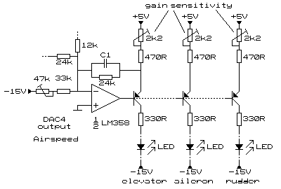
The circuit above shows the LED drive. In order to achieve a servo gain proportional to airspeed, the current to the LED that lights the LDR needs to vary with airpeed as well. I use the parallel port DAC 4th channel to drive three current sources, so that the three control channels (elevator, aileron and rudder pedals) can be controlled. Each current source has a gain-sensitivity adjustment for adjusting the force variation with airspeed for the three controls independently.

The 4th DAC channel should be assigned to airspeed via the gwbasic program,
see the Force Feedback Software examples.
The tests with the Rudder
pedals with force feedback have shown that the system works. The force
accuracy may not be perfect, but it is a huge improvement over the static
centerforce of standard pedals.
The airspeed information is now taken from Ian's motion software driver.
Currently I'm studying the addition of static (trim) and dynamic (touchdown)
effects to the force feedback system.
It should be noted that the above analog system could very well be incorporated in a micro controller chip. Flightsim data, position feedback, and servo gain control could then be done via software. I would recommend to make use of a dedicated local position feedback, as reading the the position feedback from joystick via FS leads to unacceptable delays.


