
There were a number of design considerations for the FF rudder pedals:
| Rudder pedals need considerable centering force during flight. Some tests showed that forces in the order of 150N (~15kgf) on the pedals would be needed. | |
| To make sure the centering force is felt at low force settings, the friction in the pedals must be very low. Therefore I opted for full ball bearing pivoting points. | |
| The pedals still need to have proportional brakes and the mini
transducers for wheels and engine vibration transfer. |
For the motor coupling to rudder pedals, there needs to be some gearing
ratio to obtain sufficient pedal force. The below drawing shows the basic
principle: A steel cable wound around a metal shaft will result in shaft
rotation when pedals are moved. The shaft diameter will determine the number
of rotations over full rudder movement range. The shaft needs to be strongly
attached to the frame, as it will take the full rudder pedal force.
A big gear wheel is attached to the shaft. The DC motor with a smaller gear
wheel will drive the shaft.
For the flightsim rudder input, a potmeter is mounted at the rudder bars.
The gearing is such that sufficient potmeter rotation (~180 degrees) is
obtained.
For the force feedback servo
system, a position pickup is placed at the metal shaft gearing, close to
the motor drive. This avoids servo instability due to cable slack. The
position pick-up is done with a 10-turn potmeter.
Spec of the (second hand) motor that I used: (Glentek GM2340-15)
http://www.glentek.com/glentek/dcsel.aspx
Power:
150W, torque: 0.133Nm/A, rated current : 2.5A, DC resistance 2.8 Ohms. Of
course you can use other types, but keep in mind that the motor dissipates
under stalled conditions, and will heat-up quickly.
Finding the right gear ratio proved to be quite a challenge: Originally I
started the design with a big motor gear ratio for lots of pedal force
(~200N) at relatively low motor current. This approach had the following
disadvantage: The pedals movement at zero motor current showed considerable
friction, due to the fact that the pedal movement resulted in high motor
rpm. The DC motor would act as generator, dumping current into the power
buffer supply. This resulted in unacceptable rudder pedal friction, especially
when quick rudder movements on the runway were needed.
Therefore I experimented with lower gear ratios, finally coming to a
compromise between zero drive pedal "friction" and max drive pedal force.
The total gear ratio's are now as following:
Total pedal movement is 17cm (+/- 8.5cm), total metal shaft rotation
3.4 turns (shaft diameter = 18mm), shaft gear wheel 60 teeth, motor gear
wheel 48 teeth, position pick-up 25 teeth. The motor has a torque constant
of 0.133Nm/A. The shaft has 0.133 * 60/48 = 0.166Nm/A torque. The cable
wound on the shaft has an 'arm' of 9mm. Since Force = Torque/arm, the force in the cable is
0.166 /0.009 = 18.4N/A. At 6Amps of motor current (62 *2.8 =
100W of motor power) I get ~ 111N of cable force, about 11.2 kgf. The
cables are attached at the outside of the rudder bars (230mm from center), while your feet are
slightly inward (190mm from center). This results in ~127N or 13kgf of pedal force to your feet.
Calculations and measurement results match pretty well.
The 10-turn position pick-up potmeter will rotate 8 turns, giving +/- 9.6V from centerpoint when connected to 24V.
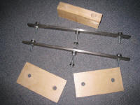
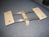
The base of the rudder pedals are two metal bars, that hold the pedals. All
pivot points have ball bearing.
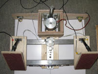
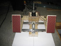

Completed pedals, including the proportional toe brakes. I added sand-paper
for anti-slip.
Toe-brake assembly: I took these out of a junked gamepad. It is mounted such
that the pedal pushes the lever.

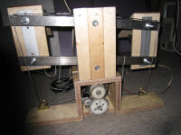
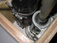
Detail of the motor to shaft gearing and servo position pick-up.
Video's of the pedals action:
Pedal movement
Gear system
Toe brakes
Servo gain (shows pedal stiffness
with increasing servo gain)
Impressions during first system test-flight in Cessna: Everything is
working as planned. On runway, the cable system with some motor friction and
slight inertia feels pretty real. During take-off, the pedals already become
stiffer. In the air, you really need some force to push the pedals. My 13kgf
seems a good figure. "Pushing the ball" now becomes more real, and
you're less prone to overdo it like I did in the past. Flying really slow
gives you some of that mushy control feeling. Best of all: There is
absolutely no delay in the force feedback with this analog servo system.
Next on my list: Adding dynamic force signals to the pedals like a sudden
sidewards jolt when touching down with slip.