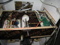
Below is a description of the yoke mechanics for adding the force feedback.
Yoke force is achieved by coupling 2 DC motors to the yoke X and Y
movements. The coupling needs to be without any slack, therefore direct
coupling via belt or steel wire is preferred.
The amount of force on the yoke depends on the motor torque, together with
the coupling ratio.
Motor selection: The quality of the force is highly depending on the type
of motors used. Most low cost DC motors show considerable fluctuation in
force when the brushes pass from one commutator to the next. This effect
becomes worse at higher motor currents. For the elevator, I had used a high
quality DC servo motor:
Spec of the (second hand) motor that I used: (Glentek GM2340-15)
http://www.glentek.com/glentek/dcsel.aspx
Power: 150W, 0.133Nm/A, rated current : 2.5A, DC resistance 2.8 Ohms
(actually I measured 4.2 ohm). Of course you can use other types, but the
torque smoothness needs to be checked carefully.

Here is a picture of the disassembled Glentek motor. As you can see
that the rotor is actually skewed, which also helps to improve the torque
smoothness.
At 3A, this motor produces 0.40Nm. with a shaft diameter of 13mm, a wire
wound over the shaft will produce a pulling force of 61.5N which is around
6.2kgf. This value is OK for most normal light GA force loading.
(For more reading on aircraft yoke force, check
this article)
For the aileron motor, I had used a smaller and less high quality motor: A Panasonic 50V/1.5A type from old copy machine ( I never buy new stuff it seems :-)
Below drawings show the position of the X and Y motors. To keep it
compact, both motors have been mounted on the moving cradle. You can check
out the Sketchup file in detail: download it
here.
A short video of the yoke movement can be downloaded here.
As you can see from the video, I had still added some passive force control on the aileron: At the extremes of the aileron movement, a bungee gets stretched. This allows for more aileron force at max position, while limiting the max required current (and subsequent force coarseness due to lower quality motor).
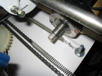
As mentioned, the coupling from motor to yoke is done via steel cables.
this needs to be done such that the wires are always tensioned, and the
winding / unwinding on the shaft needs to be smooth. Below pictures show the
details of the aileron and elevator motor coupling.


For the aileron, the steel cable can be tensioned by a bolt on the wooden
drum.
For the elevator. the steel cable can be tensioned by the 6mm bolts on both
ends of the cable that are mounted on the fixed plate below the moving
cradle.
A video of the complete system can be seen here.

