
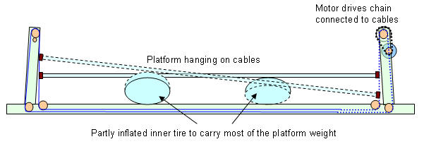
The above drawing shows the idea, which is basically the same as my original DIY motion platform I, but now the cable previously going up is folded downward to go round underneath the platform.
Further height reduction has been achieved by placing the complete cockpit on top of the platform. This has the disadvantage that the pilot is no longer sitting in the rotation point, and thus the platform is less stable. The motors will have to work somewhat harder to move the platform. To relieve the cables from carrying the full weight of the platform, a partly inflated rubber inner tire can be placed underneath the platform. Based on experiences with my first DIY motion platform, I will limit the pitch and roll angles to about +/- 10 degrees.
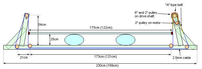
Dimensions of the folded cable construction (pitch axis) are shown above
(values between brackets are for roll axis)
Some pictures of the construction are shown below.
Getting all materials ready. The main platform is a 18mm white multiplex
board 122 x 175cm
The roll axis section of the folded cable actuator ready for some tests. All
parts come from my old DIY
platform, so progress is fast. Again, the rack-shelf metal is great for this
kind of construction.
The motor drive section. At the left the original plan, but I found that the
folded chain drive with 3 sprocket wheels has too much friction when the
cable is tensioned.
In the center an improved version:
The chain only passes the top driving sprocket wheel, then connects to cable
that passes friction-free over the wheels. Chain rattle is an issue.
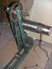
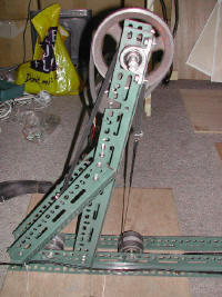
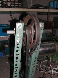
Update: Above the final version using belt-drive in stead of sprocket wheel.
This type of drive generates much less noise.
Position pick-up section, using a 10 turn potmeter, geared to the top wheel.

The two axis almost ready. Detail
of cable crossing and tensioning (needed for belt-drive)
Platform finally mounted!
Detail of platform-cable fastening
(Inner tire underneath)
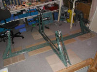
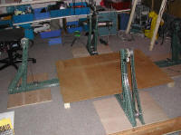

The new belt-drive installed, then adding a board, and on the board the
inner tire that holds the platform weight.
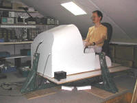 With
some effort, I got the Simpit onto the platform.
Balance is pretty close: I need some 6kg in front for balance now. With the
triple LCD + Fresnel lens display,
no extra weight should be needed.
One small glitch: the front cable support will hit the front of the Simpit
when pitching down.
Build a lightweight support for the triple LCD and Fresnel lens. Also cut a
hole at the front to clear the front support. Now the platform can
tilt and roll w/o hitting anything.
Wooden LCD frame: two 40x30mm beams hold the complete scenery view display +
fresnel lens.
It is quite sturdy.
Did some first test with 12V battery: Response OK, Platform weight carrying capability OK. The rubber inner tire indeed carries most of the weight, and also works as a mechanical 'back to center'. This helps to get the response at the extreme tilt angles more even taking the top-heavy platform load into regard. Measured pitch angle + / - 9 degrees, roll angle +/- 12 degrees.
Some tests with direct drive to check the platform response, see Motion Test Video
Finally got the whole signal chain installed! For first results see
Test Flight (two flights in the
Extra, the first in calm weather, the second with turbulence at "heavy". (I
normally make better landings, but the bumps are fantastic)
On the right side you also see the monitor with flightsim data (via Portdrv)
and the two DAC outputs on the scope (top waveform: roll and bottom one:
pitch)
Actually the test flight video shows significant jerking that is not very realistic. Further tests have shown that the roll and pitch need to be smooth and well defined. See Motion Software
During motion testing, I found the room surroundings very distracting. Although you need to have some idea of the platform's motion for troubleshooting, but the real motion effect needs to be checked with completely enclosed cockpit. Therefore I have added a structure that blocks the view of the room, and creates some feeling of being inside a small airplane.
Things I considered: lightweight, easy to shape, non-squeaking structure.
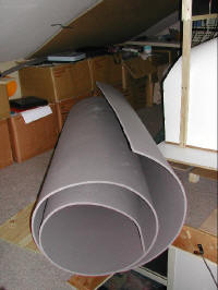
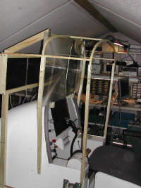
For the cover material I used 10mm thick isolation foam. (the stuff used for
camping). I needed about 3.5x1.5m. For the frame I used wood, bend in round
shape at the top to emulate the roundness of a airplane ceiling.

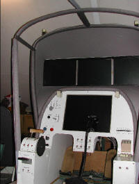
At the front, I made the cover enclose the scenery view. With the fresnell
lens, it makes the view appear out of nothing.
I covered the wooden frame with isolation tubing used for isolating hot
water pipes. It looks almost the same as the cover material, and looks much
better than the bare wooden frame.
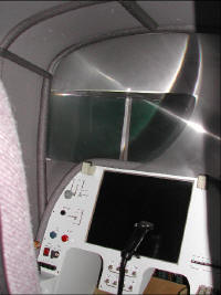
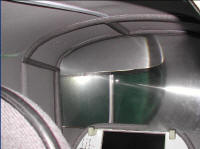
After a lot of measuring, cutting, gluing, the end result is not bad: The
foam has a similar surface as what's normally used in airplanes. It also has
some sound dampening effect. The enclosure really makes you feel being
inside of an airplane. Getting in to the structure is somewhat tricky via
the rear behind the chair, which is open. It will be necessary to add a
light of some sort, as it's a little too dark for normal daylight use.
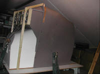
The outside of the whole structure looks weirder every time, but who cares.
Good thing is that the cover and frame can be removed, as some tweaking at
less accessible parts is always needed.
Working on adding heave. See DIY Motion Platform III page.